

For decades, cylinder head development has focused almost entirely on one thing: maximizing airflow. Bigger ports, optimized chambers, improved valve jobs and advanced CNC machining have all helped builders move more air through engines. But that approach has hit a practical wall. Eventually, the cylinder head itself cannot improve further without considering everything surrounding it, especially the valvetrain components that must work in harmony with it.
A new design philosophy is changing how engineers think about cylinder heads. Instead of designing a port first and then forcing valvetrain components around it, leading builders are now doing the opposite: they identify exactly where the valves and valvetrain need to be, then optimize the port around those fixed positions. This shift represents a fundamental rethinking of what cylinder head performance actually means.
Starting with the Non-Negotiables
The process begins by identifying what are called non-negotiables: the dimensions that cannot change. Head bolt patterns, bore centers, lifter locations, valve cover designs and class-mandated port heights all create fixed boundaries. Rather than fighting these constraints, modern cylinder head design embraces them as the starting framework.
Once those fixed points are established, designers focus on the single non-negotiable that actually can be changed: the valvetrain itself. While a lifter location may be locked into a particular position by the block, rocker arm placement can be altered. Valve locations and angles can be reconsidered. Pushrod positions can shift. This flexibility allows designers to control the entire path from the camshaft to the valve.
The ultimate goal is remarkably simple yet powerful: a pushrod that operates as straight as possible both side-to-side and front-to-back. Once that position is established, the intake port can be developed around the available pushrod window, rather than the reverse. As one leading engine shop notes, most traditional approaches force pushrods into the engine after the port is already designed, which often creates unnecessary compromises.
Valve Placement as the Foundation
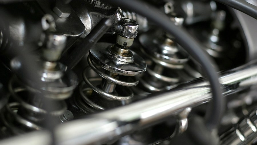
Determining the correct valve location has become one of the most time-consuming and critical portions of a new cylinder head project. Engineers may spend two weeks to a month simply establishing proper valve positions. One particularly important dimension is the valve’s pierce point, where the valve centerline intersects the deck surface. This point’s location relative to the bore and the valve’s rotation influence countless other dimensions within the head.
This is why valve angle should never be viewed as just a specification in a catalog. Moving from a 23-degree arrangement to 17 or 15 degrees changes much more than the angle at which the valve sits in the combustion chamber. It ripples through port shape, intake manifold alignment and the entire spatial relationship of all valvetrain components.
Recent developments demonstrate this flexibility in action. A new conventional-style aluminum big block cylinder head was designed around a 4.375-inch bore instead of the traditional 4.600-inch or larger. This smaller bore requires smaller valves, yet designers are still targeting the same airflow as larger-bore combinations. The smaller port cross-sectional area combined with a longer-stroke engine is intended to significantly improve torque while maintaining comparable horsepower. This example shows why cylinder head geometry cannot be separated from the engine beneath it. Bore, stroke, valve location, valve diameter, port area and valvetrain geometry are all pieces of one integrated puzzle.
Breaking Block Limitations
However, there is still a major limitation: the block itself. Cylinder heads have effectively gone as far as existing block architecture will allow. This realization prompted a radical rethinking of block design. One innovative approach raised the camshaft location to 1.053 inches above the traditional position, providing room for larger cam cores without cutting into cylinder walls.
Modern EOS cast blocks now accommodate up to nine cam bearing locations instead of the conventional five. Additional material was placed around lifter bores to allow substantially larger lifter bushings. These changes suddenly give cylinder head and valvetrain designers options that previously did not exist.
In one application, desired lifter locations interfered with conventional cam bearing positions. Instead of forcing a compromise, engineers eliminated the three conventional center cam bearing locations and added four bearings in different positions. The finished combination uses six cam bearings positioned according to the engine’s specific needs rather than allowing tradition to dictate placement. The result was nearly 4 inches of separation between lifters on each cylinder despite retaining a 4.400-inch bore center, an enormous amount of design freedom within a small-block package.
Manufacturing Precision Enables Complex Design
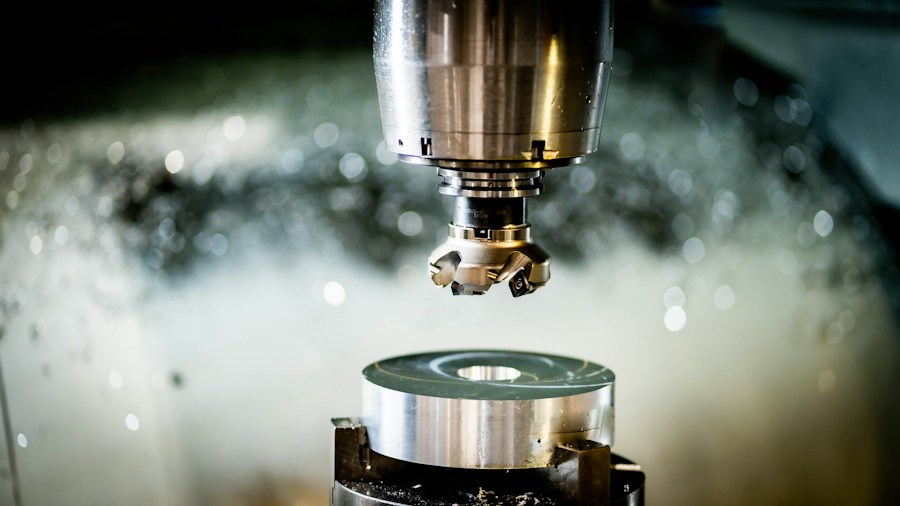
This advanced design philosophy would be useless without manufacturing capability to match it. Modern billet cylinder head designs now rely on 100 percent CAD development, which allows testing before any machining begins. Computer modeling can identify interference issues and concepts that simply will not work before committing expensive material and time. Builders estimate CAD gets approximately 97 to 98 percent of the way toward a finished design, with real-world testing determining that final few percent.
Five-axis machining centers have proven particularly well suited to cylinder head manufacturing. The combination of advanced CAD and precision machining has become essential as valve angles, rocker locations and port architecture become less conventional. Complex geometry is only valuable if it can be reliably transferred from a computer model into a repeatable, manufactured component.
What This Means for Buyers and Builders
Today’s performance builders have access to cylinder head designs that challenge traditional assumptions about what is possible. This approach is particularly relevant as racing engines demand greater RPM, airflow and output from architectures that trace their basic dimensions back 40 or 50 years.
For buyers and builders, this means asking better questions about cylinder head selection. Instead of focusing solely on port size or airflow numbers, consider how the head integrates with your specific block, bore size, stroke length and valvetrain configuration. The performance gains increasingly come from looking beyond the port itself and considering the cylinder head as part of a larger mechanical system. Sometimes making more power begins with something as straightforward as making the pushrod straight.










Write Your Review
No reviews yet. Be the first to share your experience!